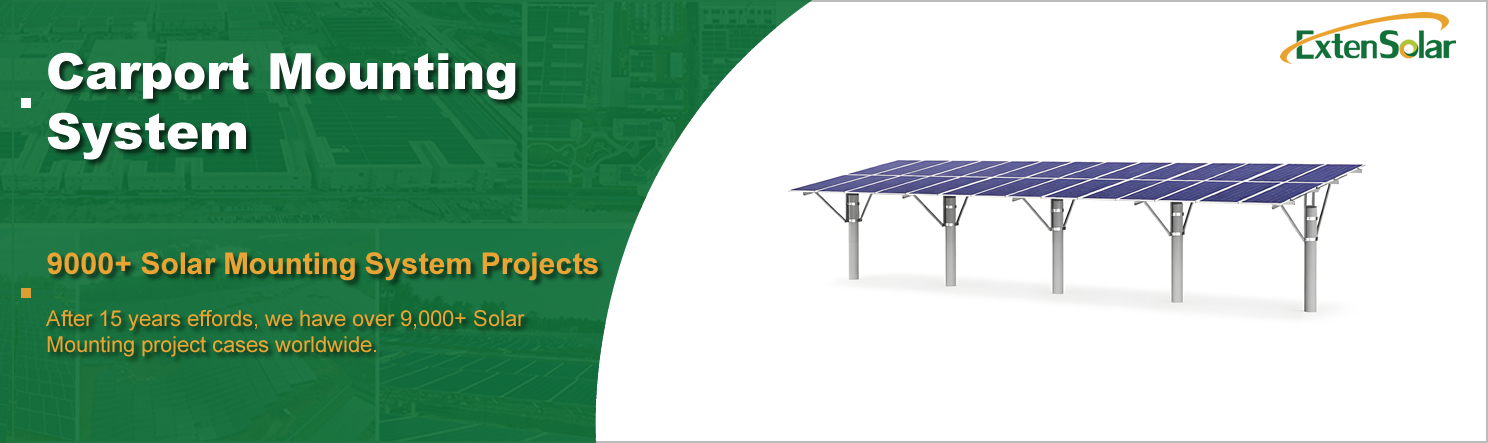
Details
| Surface Treatment |
Anodized |
Material |
Carbon steel Mg-Al-Zn Coating / Hot-dip galva ized |
| Place of Origin |
China |
Installation Site |
Open Field |
| Brand Name |
Exten |
Model Number |
A02-1 |
| Standard |
|
Certificate |
AS/NZS1170.2/CE/ISO |
| Wind Load |
60m/s(196.85ft/s) |
Module Orientation |
Landscape Portrait |
| Wind speed |
Yo 60m/s |
Max Snow Load |
1.4KN/m2 |
| Snow Load |
1.4KN/m2(29.24psf) |
Service Life |
25YRS |
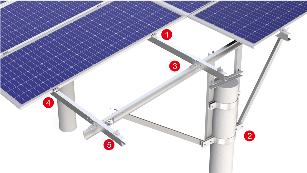
Component List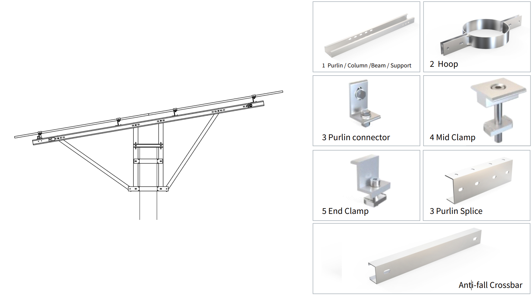
| Description |
Material |
Specificatioin |
Quantity |
| Purlin1 |
Q235B |
7795mm |
4 |
| Purlin1 |
Q235B |
8531mm |
4 |
| Beam |
Q235B |
4104mm |
5 |
| Column 1 |
Q235B |
1234mm |
5 |
| Column 2 |
Q235B |
1311mm |
5 |
| Beam Support 1 |
Q235B |
1756mm |
5 |
| Beam Support 2 |
Q235B |
1635mm |
5 |
| Anti-fall Crossbar |
Q235B |
520mm |
5 |
| Horizontally Support |
Q235B |
5400mm |
4 |
| Purlin Splice |
Q235B |
300mm |
4 |
| Pull Rod Connector |
Q235B |
50mm |
8 |
| Purlin Connector |
Q235B |
60mm |
20 |
| Hoop |
Q235B |
858mm |
10 |
| Hoop |
Q235B |
656mm |
10 |
| End Clamp |
AL 6005-T5 & SUS 304 |
80mm |
8 |
| Mid Clamp |
AL 6005-T5 & SUS 304 |
80mm |
52 |
Solar Panel Pole Mount Overview
The carbon steel solar panel pole mount is a ground-mounted photovoltaic installation structure that uses one or more vertical steel poles as its core support elements. The columns are secured via concrete foundations or buried directly into the ground, with an adjustable-tilt support frame connected to their upper ends to elevate the solar modules a certain height above the ground. The design philosophy of this system is to achieve a reliable load-transfer path using the fewest possible structural components. It is particularly suitable for complex project scenarios involving significantly undulating terrain, sites with poor ground levelness, or situations requiring elevated installation; its structural simplicity and adaptability to site conditions are its core strengths.
Why Use Pole Mount Solar Array?
Terrain adaptability far exceeds that of conventional mounts. Pillar mounts utilize independent foundations, allowing the height of each pillar to be adjusted according to the actual terrain without the need for large-scale site leveling. On mountainous terrain with slopes exceeding 15 degrees, in abandoned mines crisscrossed by ravines, or on undeveloped land with severe surface undulations, this system can still be rapidly deployed, significantly reducing earthwork and environmental impact.
The elevated design frees up ground space. Photovoltaic modules are raised to a clearance height of two meters or higher, leaving the space below completely open. This feature is particularly critical in agrivoltaic projects, allowing crops to grow normally and farm machinery to pass freely, thereby enabling dual land use. In pastoral areas, the space beneath the support structure provides shade and room for livestock to roam, without altering the original land use characteristics.
The structural load-transfer path is clear and reliable. Loads are transferred from the PV panels through support beams to the columns, and then transmitted to the foundation via the base. The stress state of each column is independently controllable, and the design calculation model is simple and straightforward. This “multi-point distributed load-bearing” approach ensures that, even under extreme wind and snow conditions, the failure of a single point will not trigger a total collapse, providing a high degree of structural redundancy.
The material offers significant strength advantages. The yield strength of carbon steel typically exceeds 350 MPa, far surpassing that of lightweight materials such as aluminum alloy. This means that, under the same load-bearing conditions, the support columns can utilize smaller pipe diameters or thinner walls, thereby reducing material consumption. Additionally, carbon steel’s high modulus of elasticity ensures excellent control of structural deflection, keeping the module installation plane stable under long-term wind-induced vibrations.
Outstanding economic performance over the entire life cycle. Carbon steel material costs are stable, supply channels are well-established, and manufacturing processes are highly standardized. After optimization, the steel consumption per tile for the column-mounted support system offers a significant cost advantage. Furthermore, the structural design life exceeds 25 years; during this period, maintenance is minimal—requiring only periodic checks of fastener torque—and operating costs remain manageable.
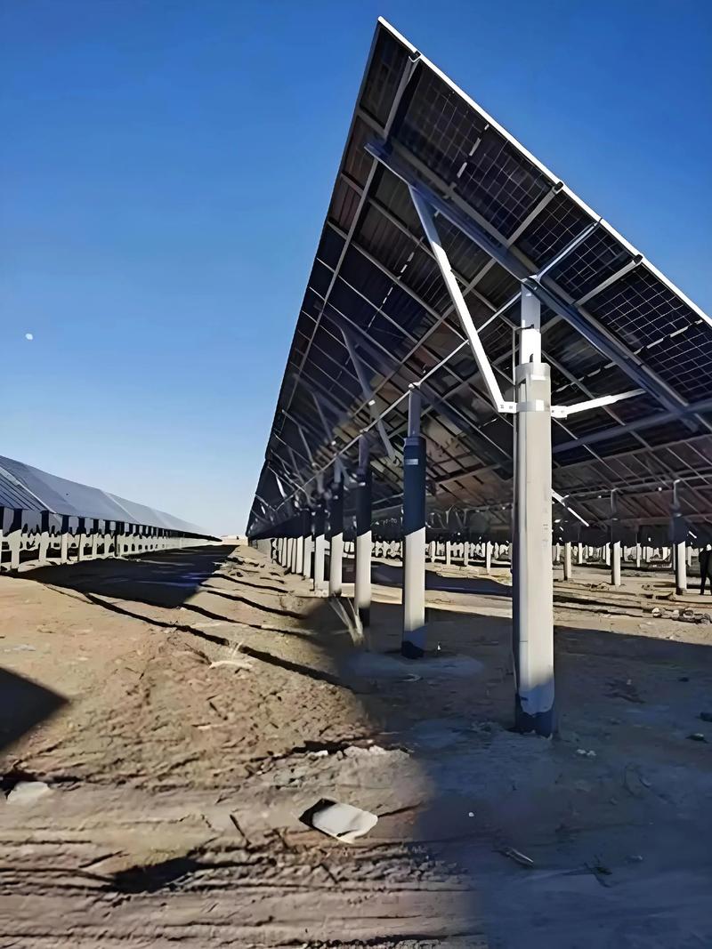
Solar Power Pole Mount Case
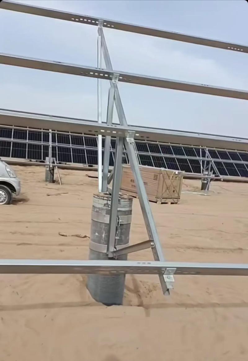
Installation Process
Step 1: Site Survey and Foundation Layout. Based on the design drawings, mark the center position of each column foundation point by point on-site. Verify the coordinates using a total station or GPS surveying equipment to ensure that positional deviations remain within acceptable limits.
Step 2: Foundation Construction. Excavate the foundation pit according to the plan determined by the geological report, tie the reinforcing bars, install the embedded anchor bolts, pour the concrete, and cure it to the design strength. For directly buried columns, anchor the lower part of the column to the bearing layer by drilling or driving.
Step 3: Column Hoisting and Verticality Adjustment. Hoist the carbon steel columns into position at the foundation sites. Use a level and theodolite to correct verticality, maintaining a deviation of no more than one thousandth. Subsequently, tighten the foundation connection bolts or backfill and compact the soil around the embedded section.
Step 4: Assembly of the Upper Support Structure. Install the main horizontal beams and diagonal braces at the top of the columns to form a load-bearing frame. Tighten all bolted connections to the design torque values and mark them for later acceptance inspection.
Step 5: PV Module Installation and System Acceptance. Secure the modules to the support frame using aluminum alloy rails and clamps, and complete grounding jumpers and equipotential bonding tests. Perform a final torque verification on all structural connection points. After confirming everything is correct, clean up the site and hand it over to the electrical commissioning team for pre-grid-connection testing.
FAQ
Q1: For which types of geological conditions are post-mounted racks suitable?
A1: This system is suitable for a variety of geological conditions, ranging from clay and sandy soil to gravelly soil. The specific foundation type must be designed based on the soil’s bearing capacity. For rocky foundations, anchor bolt foundations can be used as an alternative to traditional concrete foundations.
Q2: What is the adjustment range for the support’s tilt angle?
A2: Through the adjustable joint at the top of the column, the component’s tilt angle is typically continuously adjustable within a range of 10 to 60 degrees, meeting the design optimization needs of PV systems in regions with varying latitudes.
Q3: Do carbon steel posts require corrosion protection?
A3: Yes. Standard products are protected by hot-dip galvanizing or a magnesium-aluminum-zinc alloy coating. The coating thickness is determined based on the project’s corrosion environment classification to ensure the mounting system remains free from structural corrosion failure throughout its 25-year service life.
Q4: What is the wind resistance capacity of the post-mounted system?
A4: The design wind speed is typically verified at 160 kilometers per hour, though the specific value is determined based on meteorological data for the project site. The burial depth of the columns and the foundation dimensions will be adjusted accordingly to ensure that the resistance to uplift and lateral displacement meets safety requirements.
Q5: Does the installation process require large-scale lifting equipment?
A5: Individual columns are of moderate weight, so small crawler cranes or excavators are typically sufficient for lifting and positioning. For sites with limited terrain, installation can also be performed manually with the aid of simple lifting devices.


